Full Wave Rectification Circuit Diagram
Full wave rectifier circuit working and theory Rectifier circuit diagram half wave full wave bridge etechnog Rectifier circuit principle ac
full wave rectification diagram - Wiring Diagram and Schematics
Full wave bridge rectifier circuit convert ac voltage to dc pcb designs Full wave rectification circuit diagram Single phase half wave rectifier- circuit diagram,theory & applications
Full wave rectifier circuit
In-depth guide to full wave rectifierBridge rectifier circuit, construction, working, and types Full wave rectification diagramFull wave rectification diagram.
Full wave rectifier graphRectifier disadvantages advantages electronicscoach Rectifier circuit diagramRectifier transformer tapped output input waveform.
![full wave rectification diagram - Wiring Diagram and Schematics](https://i2.wp.com/circuitglobe.com/wp-content/uploads/2015/12/HALF-WAVE-AND-FULL-WAVE-RECTIFIER-FIG-1-compressor.jpg)
Full wave rectifier what is it circuit diagram and formula
What is full wave rectifier ?Rectifier capacitor signal waveform circuitglobe resistor robhosking Half wave & full wave rectifierHalf wave rectification circuit diagram.
Circuit diagram for full wave rectifierExplain full wave bridge rectifier with diagram pcb designs Full wave rectifier basics, circuit, working & applicationsWhat is full wave rectifier circuit diagram working advantages.
![What Is Full Wave Rectifier Circuit Diagram Working Advantages - Riset](https://i2.wp.com/circuitglobe.com/wp-content/uploads/2015/12/CENTER-TAPPED-FULL-WAVE-RECTIFIER-FIG-1-compressor.jpg)
Rectifier wave circuit full theory capacitor working load rl voltage do bridge diagram calculate output half dc its types
With neat circuit diagram and waveforms explain the operation of full12+ draw the circuit diagram of full wave rectifier All about full wave rectifier.
.
![full wave rectification diagram - Wiring Diagram and Schematics](https://i2.wp.com/www.electroduino.com/wp-content/uploads/2021/04/What-is-Full-Wave-Rectifier-Working-Principle-Circuit-Diagram-Waveforms.jpg)
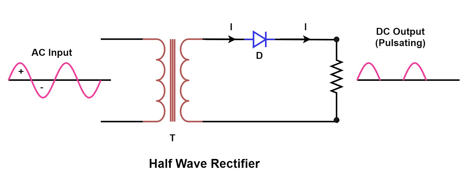
![Rectifier Circuit Diagram Half Wave Full Wave Bridge Etechnog | My XXX](https://1.bp.blogspot.com/-bTCLeh50vOE/YO6z8d2H3zI/AAAAAAAABMs/w7vO2Gw8nTcJVMMKq1r3cBeyP8caaUywwCLcBGAsYHQ/s16000/Half%2BWave%2BRectifier%2BCircuit%2BDiagram.png)
![Bridge Rectifier Circuit, Construction, Working, and Types](https://i2.wp.com/www.electronicsforu.com/wp-contents/uploads/2017/08/full-wave-rectifier-circuit.png)
![Full Wave Rectifier Basics, Circuit, Working & Applications](https://i2.wp.com/how2electronics.com/wp-content/uploads/2022/09/Full-Wave-Bridge-Rectifier.jpg)
![テスト ヤフオク! - WE 412A FULL WAVE RECTIFIER 1 PCS MINT テスト](https://i2.wp.com/www.elprocus.com/wp-content/uploads/2015/01/21-300x223.jpg)
![In-Depth Guide to Full Wave Rectifier - Circuit Diagram, Waveform](https://i2.wp.com/www.tutoroot.com/blog/wp-content/uploads/2023/03/e2-1024x1024.png)
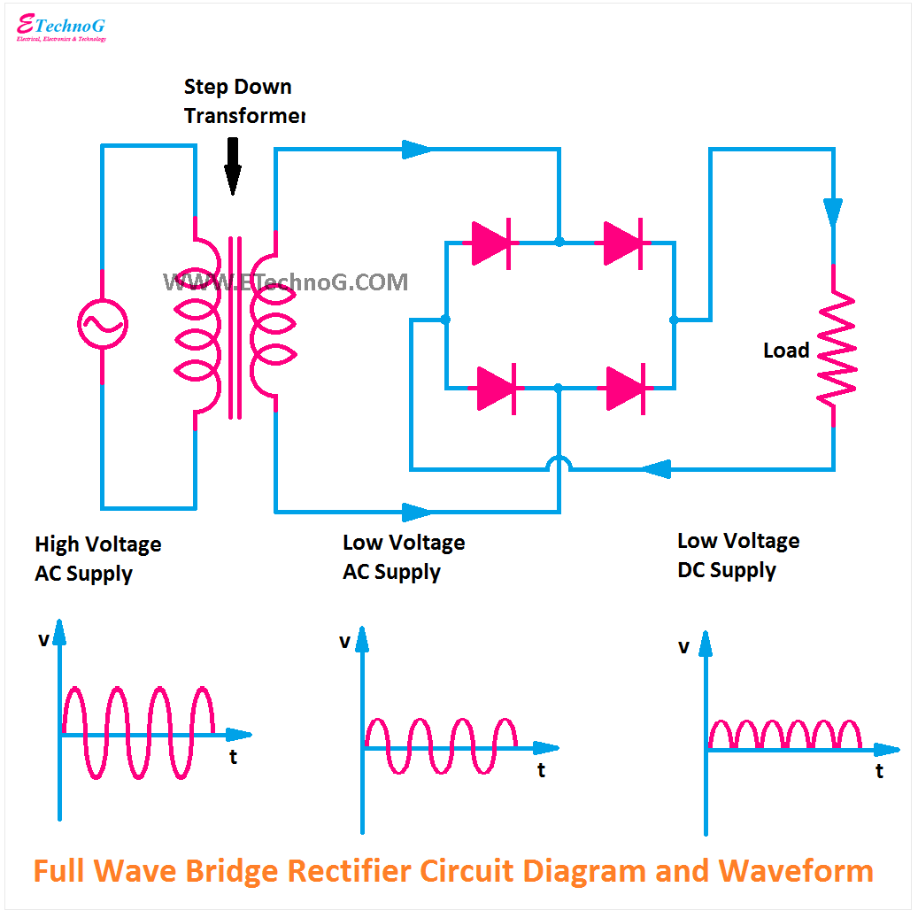
![Full Wave Bridge Rectifier Circuit Convert Ac Voltage To Dc Pcb Designs](https://i2.wp.com/circuitglobe.com/wp-content/uploads/2015/12/FULL-WAVE-BRIDGE-RECTIFIER-FIG-5-compressor.jpg)
![Single Phase Half Wave Rectifier- Circuit Diagram,Theory & Applications](https://1.bp.blogspot.com/-NLikSO8goCQ/XsuVmIxdbGI/AAAAAAAAC40/DtPRAneVEIsh1lkv2vjdhUcYMRHdbJehwCLcBGAsYHQ/s1600/Rectifier-Page-6.jpg)
![Full Wave Rectifier Circuit](https://1.bp.blogspot.com/-uzWX38U8Hjs/YO60pnoF8UI/AAAAAAAABM8/otQyNJpK8PIUk9vmeOwTroo0cMf9xL06ACLcBGAsYHQ/s16000/Full%2BWave%2BBridge%2BRectifier%2BCircuit%2BDiagram.png)
![Rectifier Circuit Diagram | Half Wave, Full Wave, Bridge - ETechnoG](https://1.bp.blogspot.com/-ph3wPcxTMhg/YO60L9F14dI/AAAAAAAABM0/svLo3j9BnrEtn4_4Ldv94ZgxqVJXvAE7ACLcBGAsYHQ/s1035/Center%2BTap%2BFull%2BWave%2BRectifier%2BCircuit%2BDiagram.png)